 Technical data >
Thermic calculations > Adjustment of the CCHC

 Adjustment according to the temperature of utilization
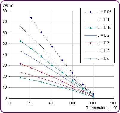
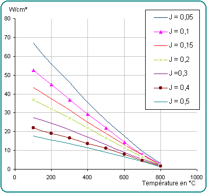
Charts of the maximum adjustments for the
assembly of the CCHCs according to the temperature of utilization :
- The curbs, given for information only, represent the limits
not to be exceeded. They integrate many thermal and expansion
parameters, but in no case they can replace real tests on an
installation.
- The ON/OFF cycles reduce the heaters' life.
- When the number of cycles is superior to : once an hour,
multiply the maximum acceptable charge by 0.8 and for once a
minute, multiply the charge by 0.7.
- Example : for an utilization at 500°C (932°F) and a
hole fit of 0.1mm, the charge must be lower than 30W/cm²
(193W/in²) and with a regulation of 1 cycle/mim, it must be
lower than 21W/cm² (135W/in²).
Charts of the maximum
adjustments for CCHC Ø6,35 to 20
|
For CCHC Ø 1/4" - 3/8" |
|
|
Ø 6,5 - 8 - 10 |
J = maximum fit |

|
For CCHC Ø 1/2" - 5/8" - 3/4" |
|
|
Ø 12,5 - 16 - 20 |
J = maximum fit |

If the specific charge of the selected
cartridge is higher than the charge shown on the charts, you will
have to make the following modifications :
- Use a larger number of cartridges with a lower specific
charge.
- Use a cartridge which is longer or with a bigger diameter.
- Reduce the hole fit of assembly as far as it is possible.
- Permit a longer rise of temperature and reduce heat losses
with a good thermal insulation.
The regulation of temperature is an important factor to consider.
The on/off control is often used.
Regulations with thyristor are the best and permit a longer life as
they eliminate the on/off cycles.
- Protect the connection leads from liquid projections and
wear possibilities.
- Avoid that wires go into the casing which holds the
cartridge.

 Technical drawing
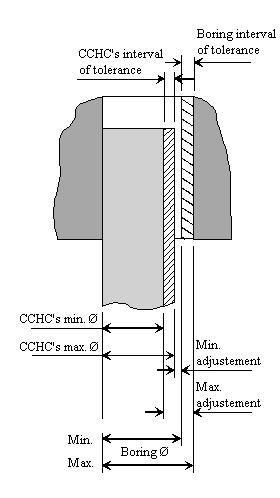
During the definition of the adjustment, take into
account the CCHCs' tolerances and the boring, taking the
most unfavorable case, that is :
The min. Ø of the CCHC
The max. Ø of boring
Example :

Alésage = boring
Ajustement = adjustment
|
 |

 Schematization of the boring's intervals of tolerance compared with the CCHC
 |
Mind out :
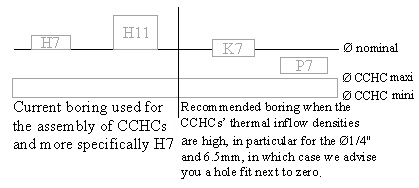
Refer to the adjustment charts according to the temperature and
the charge (W/cm2). |
|
Nominal
Ø |
CCHC's
tolerance |
Boring |
|
H7 |
H11 |
K7 |
P7 |
| Tolerance |
Adjustment
max.
min. |
Tolerance |
Adjustment
max.
min. |
Tolerance |
Adjustment
max.
min. |
Tolerance |
Adjustment
max.
min. |
| 6.35 - 6.5 |
-0.03
-0.05 |
+0.015
0 |
0.03
0.045 |
+0.09
0 |
0.03
0.14 |
+0.005
-0.010 |
0.02
0.055 |
-0.009
-0.024 |
0.006
0.041 |
| 8 |
-0.04
-0.06 |
+0.015
0 |
0.04
0.075 |
+0.09
0 |
0.04
0.15 |
+0.005
-0.010 |
0.03
0.065 |
-0.009
-0.024 |
0.016
0.051 |
| 9.52 - 10 |
-0.04
-0.07 |
+0.015
0 |
0.04
0.085 |
+0.09
0 |
0.04
0.16 |
+0.005
-0.010 |
0.03
0.075 |
-0.009
-0.024 |
0.016
0.061 |
12.5 - 12.7
15.87 - 16 |
-0.05
-0.08 |
+0.018
0 |
0.05
0.098 |
+0.11
0 |
0.05
0.19 |
+0.006
-0.012 |
0.038
0.086 |
-0.011
-0.029 |
0.021
0.069 |
| 19.05 - 20 |
-0.06
-0.10 |
+0.021
0 |
0.06
0.121 |
+0.13
0 |
0.06
0.23 |
+0.006
-0.015 |
0.045
0.106 |
-0.014
-0.035 |
0.025
0.086 |

|